If you are new to this blog, I suggest starting above with Project 1975 or Cafe Concept (on mobile devices, click the 'home' bar above for other pages).
Blog posts are in reverse order; to start from oldest to newest page, select May 2016 from the blog archive on the right. Or skip right to the completed project under 'Final Reveal' above.
Showing posts with label Moto Guzzi. Show all posts
Showing posts with label Moto Guzzi. Show all posts
Tuesday, February 28, 2017

Charging Troubleshoot
Feb 2017
Two miles from the end of a 72 mile ride, I briefly stalled the 850T at a light and could not get it restarted. The battery appeared flat as the starter just clicked and would not turn over. Quickly assessing traffic and noting a very slight downhill, I snicked it into second gear and duck-walked just enough to bump start it to life. Very relieved, those last two miles had me giving thanks that I had not stalled it earlier in the ride, and/or somewhere on a flat grade.
A check of the battery at home proved that there was a fault in the charging system; it was only 10.5V, having left before the ride with at least 12.5V. It had been charging properly at last check about 6 months earlier. Consulting several troubleshooting guides, I got to work to trace the usual suspects and identify the problem. The charging system is essentially made up of four parts. The rotor and stator take rotational energy from the crankshaft and turn it into AC power, upwards of 100V per phase depending on the type. The regulator and rectifier (r/r) cut off the AC peaks and restrict the DC output to a range that the battery can handle (roughly 12.5V to 14.5V).
First check, what's coming out of the r/r? At first I got a few erratic swings, one of which was up to 18V*. Later trying again the expected voltage of 14.5V was not reaching the battery when the engine was revved up to 4000 rpm (staying somewhat flat at 12.5V). But the solid state r/r was then ruled out when resistance and diode measurements using a multimeter figures checked out as expected. Then, resistance of the rotor windings measured between the copper slip rings also checked out, as did grounding of the rotor. And then, resistance between the phases and grounding of the stator was measured. This too checked out. A final test involved running the bike again and revving from idle while measuring AC voltage output from each of the yellow phase wires. Something was clearly up when only 3V was registering in each of the phases. These should be showing at least 50V AC each at higher rpm.
So this pointed to a bad rotor or a bad stator; stators are not known for breaking, but rotors are (averaging around 40K miles or so). But, both of these independently produced normal readings in testing.
This puzzled me for some time, prompting follow up with Gregory Bender who provided the wiring harness. His prime suspect was the rotor, but also ensured that I check r/r grounding. While re-doing several of the charging system diagnostic checks, I realized that one thing was overlooked. The rotor resistance had been taken directly via the copper slip rings, but the leads to the brushes which contact these rings were not routine items on the checklist(s). Sure enough, one was measuring contact and the other nothing. As these are hard to inspect while mounted, I pulled the alternator off the rotor. The second photo below shows the significance of the contact problem. The forward brush was worn to a nub; there was no more pressure that the spring could provide to push it down (inside the white plastic housing) enough to contact the rotor. As the charging system had worked many rides earlier, this slowly got to a point where contact was lost. Again, thankfully it came to light in a place and circumstance where I could resolve it without being stranded.
So new brushes arrived, and once installed the output of the stator is back to ~50V per phase. However, the r/r is putting out over 18V at 4000 rpm, so back to diagnostics again (has to be a dodgy r/r**)!
Pretty routine stuff on any bike, modern or classic, actually, but another example of the many potential issues and problems that are commonly associated with riding and maintaining a motorcycle.....
*(failing brush connection discovered later helps explain both erratic readings and eventual flat voltage)
**(r/r returned to manufacturer; testing revealed it was faulty, and they replaced it under warranty)
Two miles from the end of a 72 mile ride, I briefly stalled the 850T at a light and could not get it restarted. The battery appeared flat as the starter just clicked and would not turn over. Quickly assessing traffic and noting a very slight downhill, I snicked it into second gear and duck-walked just enough to bump start it to life. Very relieved, those last two miles had me giving thanks that I had not stalled it earlier in the ride, and/or somewhere on a flat grade.
A check of the battery at home proved that there was a fault in the charging system; it was only 10.5V, having left before the ride with at least 12.5V. It had been charging properly at last check about 6 months earlier. Consulting several troubleshooting guides, I got to work to trace the usual suspects and identify the problem. The charging system is essentially made up of four parts. The rotor and stator take rotational energy from the crankshaft and turn it into AC power, upwards of 100V per phase depending on the type. The regulator and rectifier (r/r) cut off the AC peaks and restrict the DC output to a range that the battery can handle (roughly 12.5V to 14.5V).
First check, what's coming out of the r/r? At first I got a few erratic swings, one of which was up to 18V*. Later trying again the expected voltage of 14.5V was not reaching the battery when the engine was revved up to 4000 rpm (staying somewhat flat at 12.5V). But the solid state r/r was then ruled out when resistance and diode measurements using a multimeter figures checked out as expected. Then, resistance of the rotor windings measured between the copper slip rings also checked out, as did grounding of the rotor. And then, resistance between the phases and grounding of the stator was measured. This too checked out. A final test involved running the bike again and revving from idle while measuring AC voltage output from each of the yellow phase wires. Something was clearly up when only 3V was registering in each of the phases. These should be showing at least 50V AC each at higher rpm.
So this pointed to a bad rotor or a bad stator; stators are not known for breaking, but rotors are (averaging around 40K miles or so). But, both of these independently produced normal readings in testing.
This puzzled me for some time, prompting follow up with Gregory Bender who provided the wiring harness. His prime suspect was the rotor, but also ensured that I check r/r grounding. While re-doing several of the charging system diagnostic checks, I realized that one thing was overlooked. The rotor resistance had been taken directly via the copper slip rings, but the leads to the brushes which contact these rings were not routine items on the checklist(s). Sure enough, one was measuring contact and the other nothing. As these are hard to inspect while mounted, I pulled the alternator off the rotor. The second photo below shows the significance of the contact problem. The forward brush was worn to a nub; there was no more pressure that the spring could provide to push it down (inside the white plastic housing) enough to contact the rotor. As the charging system had worked many rides earlier, this slowly got to a point where contact was lost. Again, thankfully it came to light in a place and circumstance where I could resolve it without being stranded.
So new brushes arrived, and once installed the output of the stator is back to ~50V per phase. However, the r/r is putting out over 18V at 4000 rpm, so back to diagnostics again (has to be a dodgy r/r**)!
Pretty routine stuff on any bike, modern or classic, actually, but another example of the many potential issues and problems that are commonly associated with riding and maintaining a motorcycle.....
*(failing brush connection discovered later helps explain both erratic readings and eventual flat voltage)
**(r/r returned to manufacturer; testing revealed it was faulty, and they replaced it under warranty)
 |
| exposed stator/alternator on front of 850T; three yellow wires for three phases |
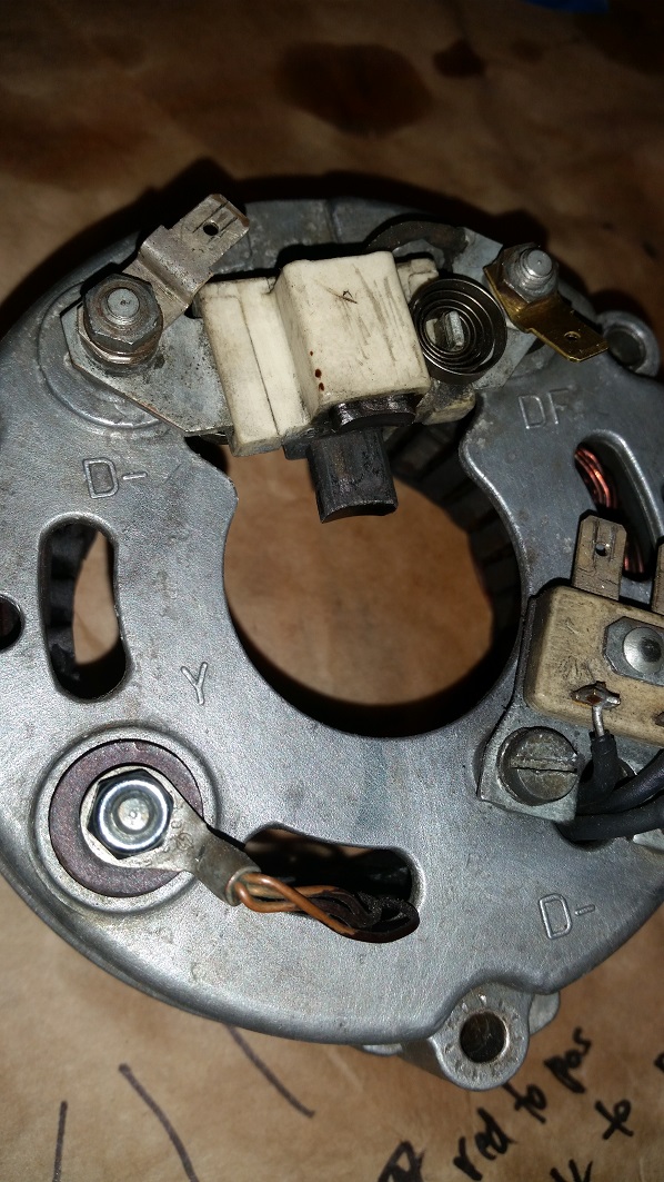 |
| a 'spring loaded' brush for each copper slip ring on the rotor; note forward brush worn to a nub |
Sunday, January 29, 2017
Got Flakes?
Early 2017 Update
It was a matter of time before the cylinders came off for inspection, and a persistent minor leak on the right was the reason this moment finally came. I had re-torqued the head a few times already with no change, so after a little procrastination I got some new gaskets on order and got to work.
 At first glance I thought all looked OK, until I noticed some
scoring on the back side of the piston. Then it was clear that one of the rings was
ground into the groove near the exhaust side and the piston was scored. A check of the
corresponding cylinder bore location revealed an unsettling mark. Crud, the chrome
had flaked off in an area about the size of a 'Tic Tac'. This cylinder is toast. And a little scary at how close it might have been to failure, had I not checked.
At first glance I thought all looked OK, until I noticed some
scoring on the back side of the piston. Then it was clear that one of the rings was
ground into the groove near the exhaust side and the piston was scored. A check of the
corresponding cylinder bore location revealed an unsettling mark. Crud, the chrome
had flaked off in an area about the size of a 'Tic Tac'. This cylinder is toast. And a little scary at how close it might have been to failure, had I not checked.


Options ranged from sourcing used jugs, to NOS cylinders, to new Gilardoni cylinders. And with or without pistons? Rings? Since an eBay search showed several reasonable used items, I decided to go the cheapest route (my usual!) and buy used. Including the pistons, which is good, as the scoring on my right piston has gone a little far for comfort. I hope the photos and descriptions live up to the condition required to use them. More when they arrive and the installation is done.
Follow-up: the used cylinder arrived, with chrome bores in very good condition. And, the piston with which it is matched is in good shape, and the rings are free from obvious wear and move freely in their grooves. Wrist pin also looks great; that was popped into the freezer for later installation.


Both needed a lot of cleaning, however; mud wasp nests and corrosion from the cylinder and carbon from the piston head. My soda blaster was put to use as well, helping to strip decades of build-up; a water bath then neutralized the soda and all was dried. Following the thorough scrub and cleaning (and aluminum paint on cylinder fins), it was time to install the piston, gaskets and put the head on. I'd never held the 'beating heart' of a motor in my hands before, so was a little nervous about putting this all back together. I further did not expect the wrist pin (a press fit) to be so snug. A tool had to be made to press the old one out and the new one in (and installing it fresh out of the freezer overnight helped as well). Below photos show the tool in action pressing the old one out, and then the parts of the tool. Next time I will use a more robust bit of PVC tubing, but this worked well and I got the new piston installed without too much effort.


The head bolts had to be torqued properly before the valve clearance adjustments could be made. While cold, the head was bolted down in a star pattern until very snug, but just under full torque. At roughly 24 hours, the head was torqued to 34 pd/ft. Then again, roughly 24 hours later the head was re-torqued to the same 34 pound feet. Valve clearances were then both set at 0.006" (slightly tighter than Guzzi spec, I know). Other note, both were at first measuring tight from prior setting, as evidence that the new gaskets are (obviously) not quite as compressed as the old ones were. A day later I took the 850T out for a ride; it started quickly as usual and settled into an idle. It rides at least as well/normally as before; revving easily no smoking or oil leaks. Hooray!!
It was a matter of time before the cylinders came off for inspection, and a persistent minor leak on the right was the reason this moment finally came. I had re-torqued the head a few times already with no change, so after a little procrastination I got some new gaskets on order and got to work.


Options ranged from sourcing used jugs, to NOS cylinders, to new Gilardoni cylinders. And with or without pistons? Rings? Since an eBay search showed several reasonable used items, I decided to go the cheapest route (my usual!) and buy used. Including the pistons, which is good, as the scoring on my right piston has gone a little far for comfort. I hope the photos and descriptions live up to the condition required to use them. More when they arrive and the installation is done.
Follow-up: the used cylinder arrived, with chrome bores in very good condition. And, the piston with which it is matched is in good shape, and the rings are free from obvious wear and move freely in their grooves. Wrist pin also looks great; that was popped into the freezer for later installation.


Both needed a lot of cleaning, however; mud wasp nests and corrosion from the cylinder and carbon from the piston head. My soda blaster was put to use as well, helping to strip decades of build-up; a water bath then neutralized the soda and all was dried. Following the thorough scrub and cleaning (and aluminum paint on cylinder fins), it was time to install the piston, gaskets and put the head on. I'd never held the 'beating heart' of a motor in my hands before, so was a little nervous about putting this all back together. I further did not expect the wrist pin (a press fit) to be so snug. A tool had to be made to press the old one out and the new one in (and installing it fresh out of the freezer overnight helped as well). Below photos show the tool in action pressing the old one out, and then the parts of the tool. Next time I will use a more robust bit of PVC tubing, but this worked well and I got the new piston installed without too much effort.


The head bolts had to be torqued properly before the valve clearance adjustments could be made. While cold, the head was bolted down in a star pattern until very snug, but just under full torque. At roughly 24 hours, the head was torqued to 34 pd/ft. Then again, roughly 24 hours later the head was re-torqued to the same 34 pound feet. Valve clearances were then both set at 0.006" (slightly tighter than Guzzi spec, I know). Other note, both were at first measuring tight from prior setting, as evidence that the new gaskets are (obviously) not quite as compressed as the old ones were. A day later I took the 850T out for a ride; it started quickly as usual and settled into an idle. It rides at least as well/normally as before; revving easily no smoking or oil leaks. Hooray!!
 |
| wrist pin pressed through the rod, and cylinder about to be dropped down onto base gasket |
Take a Seat, Cover
Early 2017
Ugh. This seat issue has dragged out for far too long; besides the added effort and cost, it is interfering with riding time too! To recap, the seat and pan as purchased on bike were not stock; being made of aluminum, the pan also was losing shape and not a good platform for my project. I purchased a cafe seat which looks great, but was not designed to fit with the 4" rise of the stock rear fender. Much modification later I got it to fit, but it was too low (not a lot of leg room) and did not meet the tank in an appealing way. So the next plan was to add two inches of foam to raise the seat height and cover the seat with a stock(ish) cover. But the leather (vinyl) of the V7 style cover I bought does not stretch enough to retain the foam shape I'm looking for (cafe style similar to my after market cafe seat).
I finally realized that I'd have to cut and sew my own seat cover. Although a reasonably capable tailor, not looking forward to this.
 Starting with the fabric, I sourced a black vinyl product which has 4-way stretch; I would not characterize it as 'stretchy', merely that it has some give in it. Not a lot, however, meaning that my cover had better come very close to matching the foam shaped underneath.
Next was to finish the foam reconstruction of the seat pan to raise the height 2". This further required an extension to the front of the pan, by which I cut two strips of steel and riveted each to either side at the front. The foam also needed to be built up around the front to 'cup' the rear of the tank (dark grey section you can see in the photos).


 After a few internet searches and YouTube videos, I then tackled the hardest part of the seat cover - a quilting effect on the top. I glued 1/2" foam to the back of a piece of liner fabric and then to the piece of vinyl I'd cut out in the shape and length I needed (here, I also needed to note that I'd extended the foam top forward about 1", and measure lengths accordingly). A few practice runs using heavy duty thread had the tension off and the thread binding in the needle. I had to resort to regular black cotton thread (meaning that however this seat turns out, the stitching will not last forever....). Sounds like a good excuse to get that industrial sewing machine I'd been thinking about. So my results are as pictured below.
I was noticeably off on one row, but when stretched a little and mounted I don't think it will be a problem. Was pretty happy with how it turned out in relation to the cafe seat I'd originally purchased; except the ridges are 'higher' than I'd wanted since the foam I used was likely a little thicker - should have measured 2" between them instead of 1 3/4". That piping I had to make from scratch as well.

Next is to measure the rear and sides; but before sewing these on, I'd always really liked the Moto Guzzi logo in white across the back of the V7 cover (and other models as stock). I hand cut a stencil using clear window decal paper and purchased a can of white vinyl spray paint. The first test (yes, testing first is always a good idea!) had the paint bleeding under the stencil due to the embossed nature of the leather-looking fabric. A second test showed that dusting the paint on in a single pass (or two) with 5-10 min in between passes resulted in very little bleed. Once I started painting the cut rear fabric, it would be all over for better or worse. Level, square and no bleeding were the goals.
I'll let you know shortly how it all turned out............
Ok, it's about 2 weeks later, and about that time! The logo painting worked very well, with just a little micro-bleeding under the the stencil (not visible except very close; below). And after MUCH puzzling and planning and measurement I finally decided how the sides and front would be sewn, and committed to doing so. The only section I was prepared to mess up was the front, as any errors would be covered by the tank. Indeed, I had to pull stitching out of the front two times due to flawed estimations. The rear turned out to be tougher than the front, reverse of what I'd been expecting. I realize now that any change in surface angle or direction requires a separate section cut out for it; sewn interfaces are much easier to conform to turns and corners, etc, than relying on the stretch of the fabric alone. But I made it work. 'First' Final product below (not fully tacked down):

I was happy but not entirely so. The seat on its own looked fine, but was a little bulky looking on the bike itself. And the 90 degree turns in the back led to bunched up fabric that did not look as professional as I'd hoped for. So I did some more thinking and looking on the internet for examples of seat shapes. I realized that a gentle curve up near the tail would both reduce the bulk and avoid sharp bends and thus reduce bunched up fabric. Even more puzzling and thinking led to a plan. I had purchased several tack strips but had not used them; one of these would be needed. I realized that if I made two cuts on each side of the seat pan it could be bent upward gradually towards the top of the fender. A length of tack strip could then be riveted into place across the gap, and over top of the fender, to continue the smooth arc from one side to the other. Again, my trusty 4" cut-off wheel did quick work of it and soon the idea was tested (below).


Once the cover was stretched over the seat pan, the latch mechanism was the last element to construct. I pulled the one off the seat that came with the bike and, after several measurements, drilled the holes for rivets. These holes had very little margin for error, as they directly dictated how the seat lined up with the seat tang welded on the frame. Thankfully my measurements and estimations were good, as the fit and function are perfect.
So I can call the seat done, finally. The extra leg room and more upright seated position on the bike is noticeable and feels much better than the stretched-out, knees-under-the-armpit position from before. It is not 100% what I would wish for, but it looks very passable for a first time fabrication, and it works well. So much went into it too that it deserves to be let go of for a while at this point and just ride.......


Ugh. This seat issue has dragged out for far too long; besides the added effort and cost, it is interfering with riding time too! To recap, the seat and pan as purchased on bike were not stock; being made of aluminum, the pan also was losing shape and not a good platform for my project. I purchased a cafe seat which looks great, but was not designed to fit with the 4" rise of the stock rear fender. Much modification later I got it to fit, but it was too low (not a lot of leg room) and did not meet the tank in an appealing way. So the next plan was to add two inches of foam to raise the seat height and cover the seat with a stock(ish) cover. But the leather (vinyl) of the V7 style cover I bought does not stretch enough to retain the foam shape I'm looking for (cafe style similar to my after market cafe seat).
 |
| stock Moto Guzzi V7 seat cover |
Next was to finish the foam reconstruction of the seat pan to raise the height 2". This further required an extension to the front of the pan, by which I cut two strips of steel and riveted each to either side at the front. The foam also needed to be built up around the front to 'cup' the rear of the tank (dark grey section you can see in the photos).


 |
| finished, with piping |
 |
| compared to purchased cafe seat |

Next is to measure the rear and sides; but before sewing these on, I'd always really liked the Moto Guzzi logo in white across the back of the V7 cover (and other models as stock). I hand cut a stencil using clear window decal paper and purchased a can of white vinyl spray paint. The first test (yes, testing first is always a good idea!) had the paint bleeding under the stencil due to the embossed nature of the leather-looking fabric. A second test showed that dusting the paint on in a single pass (or two) with 5-10 min in between passes resulted in very little bleed. Once I started painting the cut rear fabric, it would be all over for better or worse. Level, square and no bleeding were the goals.
 |
| stencil placed along center line |
 |
| stencil taped for painting |
Ok, it's about 2 weeks later, and about that time! The logo painting worked very well, with just a little micro-bleeding under the the stencil (not visible except very close; below). And after MUCH puzzling and planning and measurement I finally decided how the sides and front would be sewn, and committed to doing so. The only section I was prepared to mess up was the front, as any errors would be covered by the tank. Indeed, I had to pull stitching out of the front two times due to flawed estimations. The rear turned out to be tougher than the front, reverse of what I'd been expecting. I realize now that any change in surface angle or direction requires a separate section cut out for it; sewn interfaces are much easier to conform to turns and corners, etc, than relying on the stretch of the fabric alone. But I made it work. 'First' Final product below (not fully tacked down):

I was happy but not entirely so. The seat on its own looked fine, but was a little bulky looking on the bike itself. And the 90 degree turns in the back led to bunched up fabric that did not look as professional as I'd hoped for. So I did some more thinking and looking on the internet for examples of seat shapes. I realized that a gentle curve up near the tail would both reduce the bulk and avoid sharp bends and thus reduce bunched up fabric. Even more puzzling and thinking led to a plan. I had purchased several tack strips but had not used them; one of these would be needed. I realized that if I made two cuts on each side of the seat pan it could be bent upward gradually towards the top of the fender. A length of tack strip could then be riveted into place across the gap, and over top of the fender, to continue the smooth arc from one side to the other. Again, my trusty 4" cut-off wheel did quick work of it and soon the idea was tested (below).
 |
| curve cut into seat pan (top left) to take the line up and over the rear fender |


Once the cover was stretched over the seat pan, the latch mechanism was the last element to construct. I pulled the one off the seat that came with the bike and, after several measurements, drilled the holes for rivets. These holes had very little margin for error, as they directly dictated how the seat lined up with the seat tang welded on the frame. Thankfully my measurements and estimations were good, as the fit and function are perfect.
So I can call the seat done, finally. The extra leg room and more upright seated position on the bike is noticeable and feels much better than the stretched-out, knees-under-the-armpit position from before. It is not 100% what I would wish for, but it looks very passable for a first time fabrication, and it works well. So much went into it too that it deserves to be let go of for a while at this point and just ride.......


Saturday, December 3, 2016
Sorting Stuff Out
Nov 2016 - what's next for this Moto Guzzi?
So, with the bike reassembled and the project goal accomplished, I've had the opportunity to put about 250 miles on the 850T. A few things quickly became apparent, as one might imagine; nothing unusual or troubling, just the routine experiences and observations which come from daily living with such a mechanical entity. While I can live with it just fine as is, a little attention to the following will enhance the reliability and rideability. The forks are quite undersprung and the front disc brake is very poor, like a block of wood against steel. I also found a small leak at the base of the right cylinder and the rear drive leaks as well (minor leaks are a major reason for maintaining a clean bike so, first, you are aware of a potential problem very early and, second, you can more quickly pinpoint the source). Minor issues are par for the course on a 40 year old bike - note, I do not expect it to handle like any of the other decades-newer bikes in my stable. Nonetheless, these are correctable, and things that I'd like to sort out.
The first thing is getting the cylinder leaks taken care of (leaving tiny, misted droplets on my boots after a 30 mile ride). Some brief research implies that this is normal for big block Guzzi's, and should be rectified by re-torquing the cylinder heads. After sorting through various forum exchanges I determined that the torque needs to be at least 32 lb/ft and no more than 34. Unfortunately I only have a torque wrench in inch pounds, which tops out at only 3/4 of this range. Oh well. Pictured below are the rockers under the valve cover over the left side cylinder. Another 'unfortunately', the rockers have to come off for access to two of the six bolts holding the cylinder head down. It was not difficult or all that time-consuming, but I had put it off for a few weeks as the first time doing anything carries with it a little trepidation. I could feel that the six bolts loosened fairly easily (not easy, just easily enough) - judging that they needed more torque and not having a torque wrench, I simply marked each bolt with a tiny scratch so I could confirm that it had been snugged a tad (technical unit of measure) more than before. All buttoned up again, the left side is ok but the right still has a little pool of oil collecting on the lower inside. I've since borrowed a larger torque wrench to get to this job again shortly. Ugh.

The next thing to warrant attention are the fork springs, since I'd like to correct the saggy feel and dive before addressing the disc brake. I'd removed and serviced the forks during the rebuild, and put the stock springs back in; whether they ever were in the first place, they are not quite up to the task now. I called Progressive earlier in 2016 looking for springs with a heavier spring rate for this bike. I purchased the recommended springs (0.68 kg/mm) but they were 60mm too long. Or at least they were 60mm longer than the stock springs and I was sure that they could not be compressed enough to fit. Past 90 days from purchase I could not return them, but the tech told me they could be cut down a few inches. Consulting Guzziology, it was noted that a spring should generally not be much more than 1.5 inches above the top of the damper shaft at full extension (or spacer length if setting preload). The stock springs sit at exactly the top of the shaft when not compressed. Feeling that the Progressive springs would be stiffer than stock, I elected to cut the Progressives down leaving about 1.5 inches. This was a mistake! Whether they are stiffer than stock or not, I still cannot really say. The sag is better and they are compliant and not springy, they still sag several inches under bike and rider weight and then bottom out under heavy braking.
To Resolve - the cut piece can actually be used as a spacer; either with the stock spring or the Progressive. Although the total length of the Progressive spring may be prohibitively long..... I just hate to take these on and off in a trial-and-error fashion. But I cannot identify what the spring rate of the stock spring is.... Ideally, for a bike weighing about 500lbs and a rider (me) weighing about 200lbs, a spring rate of 0.95kg/mm is called for.
And last, the seat. I somehow knew that this saga would end with me actually fabricating a seat for myself. After the shop which made the first cafe seat (too low and interferes with rear fender) promised to replace it, and then waiting another 2+ months, they won't do it. Options include buying a stock seat just for the pan, or using the cafe pan I have. I can't use the seat that came on my project as it is not original and was fabricated from aluminum, thus it doesn't hold its shape well and presents problems for attaching the seat cover. So cannibalizing my new cafe seat for the pan will be my approach. I also think I can cut off the top of the foam to retain the shape of the cafe seat, as they did quite a good job of this (and it requires patience and skill, two things I have only in limited supply).
Two dense foam pads from Home Depot (gardening kneelers) will serve as the base on top of the pan. Then the cafe padding, then I bought a roll of 1/2" foam to cover and smooth the underlying layers. From eBay, I found a Moto Guzzi V7 replica seat cover that has the words 'MOTO GUZZI' in block letters across the back. The hump is not the same, but close enough that I'm confident that it will fit (and still look "cafe") with a little tuck here and there and extra foam if necessary.
So, with the bike reassembled and the project goal accomplished, I've had the opportunity to put about 250 miles on the 850T. A few things quickly became apparent, as one might imagine; nothing unusual or troubling, just the routine experiences and observations which come from daily living with such a mechanical entity. While I can live with it just fine as is, a little attention to the following will enhance the reliability and rideability. The forks are quite undersprung and the front disc brake is very poor, like a block of wood against steel. I also found a small leak at the base of the right cylinder and the rear drive leaks as well (minor leaks are a major reason for maintaining a clean bike so, first, you are aware of a potential problem very early and, second, you can more quickly pinpoint the source). Minor issues are par for the course on a 40 year old bike - note, I do not expect it to handle like any of the other decades-newer bikes in my stable. Nonetheless, these are correctable, and things that I'd like to sort out.
The first thing is getting the cylinder leaks taken care of (leaving tiny, misted droplets on my boots after a 30 mile ride). Some brief research implies that this is normal for big block Guzzi's, and should be rectified by re-torquing the cylinder heads. After sorting through various forum exchanges I determined that the torque needs to be at least 32 lb/ft and no more than 34. Unfortunately I only have a torque wrench in inch pounds, which tops out at only 3/4 of this range. Oh well. Pictured below are the rockers under the valve cover over the left side cylinder. Another 'unfortunately', the rockers have to come off for access to two of the six bolts holding the cylinder head down. It was not difficult or all that time-consuming, but I had put it off for a few weeks as the first time doing anything carries with it a little trepidation. I could feel that the six bolts loosened fairly easily (not easy, just easily enough) - judging that they needed more torque and not having a torque wrench, I simply marked each bolt with a tiny scratch so I could confirm that it had been snugged a tad (technical unit of measure) more than before. All buttoned up again, the left side is ok but the right still has a little pool of oil collecting on the lower inside. I've since borrowed a larger torque wrench to get to this job again shortly. Ugh.

The next thing to warrant attention are the fork springs, since I'd like to correct the saggy feel and dive before addressing the disc brake. I'd removed and serviced the forks during the rebuild, and put the stock springs back in; whether they ever were in the first place, they are not quite up to the task now. I called Progressive earlier in 2016 looking for springs with a heavier spring rate for this bike. I purchased the recommended springs (0.68 kg/mm) but they were 60mm too long. Or at least they were 60mm longer than the stock springs and I was sure that they could not be compressed enough to fit. Past 90 days from purchase I could not return them, but the tech told me they could be cut down a few inches. Consulting Guzziology, it was noted that a spring should generally not be much more than 1.5 inches above the top of the damper shaft at full extension (or spacer length if setting preload). The stock springs sit at exactly the top of the shaft when not compressed. Feeling that the Progressive springs would be stiffer than stock, I elected to cut the Progressives down leaving about 1.5 inches. This was a mistake! Whether they are stiffer than stock or not, I still cannot really say. The sag is better and they are compliant and not springy, they still sag several inches under bike and rider weight and then bottom out under heavy braking.
To Resolve - the cut piece can actually be used as a spacer; either with the stock spring or the Progressive. Although the total length of the Progressive spring may be prohibitively long..... I just hate to take these on and off in a trial-and-error fashion. But I cannot identify what the spring rate of the stock spring is.... Ideally, for a bike weighing about 500lbs and a rider (me) weighing about 200lbs, a spring rate of 0.95kg/mm is called for.
 |
| above = stock spring (420mm); below = Progressive after cut (total 480mm) |
And last, the seat. I somehow knew that this saga would end with me actually fabricating a seat for myself. After the shop which made the first cafe seat (too low and interferes with rear fender) promised to replace it, and then waiting another 2+ months, they won't do it. Options include buying a stock seat just for the pan, or using the cafe pan I have. I can't use the seat that came on my project as it is not original and was fabricated from aluminum, thus it doesn't hold its shape well and presents problems for attaching the seat cover. So cannibalizing my new cafe seat for the pan will be my approach. I also think I can cut off the top of the foam to retain the shape of the cafe seat, as they did quite a good job of this (and it requires patience and skill, two things I have only in limited supply).
Two dense foam pads from Home Depot (gardening kneelers) will serve as the base on top of the pan. Then the cafe padding, then I bought a roll of 1/2" foam to cover and smooth the underlying layers. From eBay, I found a Moto Guzzi V7 replica seat cover that has the words 'MOTO GUZZI' in block letters across the back. The hump is not the same, but close enough that I'm confident that it will fit (and still look "cafe") with a little tuck here and there and extra foam if necessary.
 |
| slightly photoshopped to show where it would sit higher after modification |
Tuesday, October 11, 2016
Shifter Fix
Oct 2016
Which brings me finally to the shifter. Since last February, I'd spent hours deciding how the shifter and brake levers were going to work using the Tarozzi rearsets* (and levers) I'd purchased for the project. In brief, the stock foot peg bracket on the right of the project I'd purchased was bent, and the foot peg itself had been cut off, replaced with a threaded hole. Replacement either on eBay or new would be costly, and the aftermarket rearsets suited the cafe-style project better anyway, so I went this route. But the 1975 frame and drum rear complicated matters. I thought I had both figured out, but putting the solutions into practice turned out to be easier said than done.
This issue has hung over the project since the beginning, and it took on a more urgent nature once the bike was actually finished and ready to ride. A few short test rides quickly revealed just how much torque and force is going through the shift lever. My prior solution (see earlier posts) became more and more sloppy, and the hole I'd drilled in the stock left block plate was actually cracking. This plate is composed of some composite alloy and would not weld. My neighbor Jerry suggested fabricating a plate with a spline shaft from scratch, and although I dreaded such a drastic approach I ended up concluding that this was indeed the way to go. The alternative was to buy an $80 replacement stock block plate and return to the stock shifter (by cutting it down and adding the toe piece from the Tarozzi).
So it was, I sourced a steel plate and 5/8" ID steel bushing and drew out the required measurements. Then drilled and cut until I had a rough bracket (as below, shown with stock bracket)


Jerry provided welding expertise and after a few hours we had a finished bracket incorporating a very snug-fitting bushing for the spline shaft. All holes lined up and a test ride revealed positive shifting up and down through all the gears. Success! So now just have to dismantle, clean it up a bit more and paint before re-installing.

*footnote: the folding pegs stick out more than an inch wider than the non-folding pegs. these were far too wide for the bike, and Jim at FFTP graciously agreed to swap my pegs for a new set they'd made which were shorter. installation proved these to be a much better way to go.
Which brings me finally to the shifter. Since last February, I'd spent hours deciding how the shifter and brake levers were going to work using the Tarozzi rearsets* (and levers) I'd purchased for the project. In brief, the stock foot peg bracket on the right of the project I'd purchased was bent, and the foot peg itself had been cut off, replaced with a threaded hole. Replacement either on eBay or new would be costly, and the aftermarket rearsets suited the cafe-style project better anyway, so I went this route. But the 1975 frame and drum rear complicated matters. I thought I had both figured out, but putting the solutions into practice turned out to be easier said than done.
 |
| Tarozzi brand aftermarket rearsets & levers |
This issue has hung over the project since the beginning, and it took on a more urgent nature once the bike was actually finished and ready to ride. A few short test rides quickly revealed just how much torque and force is going through the shift lever. My prior solution (see earlier posts) became more and more sloppy, and the hole I'd drilled in the stock left block plate was actually cracking. This plate is composed of some composite alloy and would not weld. My neighbor Jerry suggested fabricating a plate with a spline shaft from scratch, and although I dreaded such a drastic approach I ended up concluding that this was indeed the way to go. The alternative was to buy an $80 replacement stock block plate and return to the stock shifter (by cutting it down and adding the toe piece from the Tarozzi).
So it was, I sourced a steel plate and 5/8" ID steel bushing and drew out the required measurements. Then drilled and cut until I had a rough bracket (as below, shown with stock bracket)


Jerry provided welding expertise and after a few hours we had a finished bracket incorporating a very snug-fitting bushing for the spline shaft. All holes lined up and a test ride revealed positive shifting up and down through all the gears. Success! So now just have to dismantle, clean it up a bit more and paint before re-installing.

*footnote: the folding pegs stick out more than an inch wider than the non-folding pegs. these were far too wide for the bike, and Jim at FFTP graciously agreed to swap my pegs for a new set they'd made which were shorter. installation proved these to be a much better way to go.
Tuesday, September 20, 2016
Lessons in Restoration
During the course of this project, I definitely came to points in the build where I'd regretted a timing or decision from an earlier junction, or after making the same mistake for the fifth time, wished for a more efficient approach. For example, I purchased several parts very early on which should have been no-brainers, but found out too late to return them that they would not work or were not right (fork springs and m/c rebuild kit for two). All in all, however, the timing and cost were not too far off my estimates. The effort required was maybe a little more than I'd hoped for. But even after much detailed planning, nothing is ever exactly what you think it will be.
Your project may be more or less involved, or may require more sophisticated design and fabrication. This 850T project called for significant disassembly and cleaning, polishing or de-rusting and painting of almost every component. Minor brackets were fabricated and solutions required for a host of aesthetic and functional elements. These are some thoughts I've had on the project as it unfolded, where I frequent uttered the words "next time", before I even knew what I was saying. Then glanced around to check that my wife was not over-hearing me, as for this one there is no such thing as a next time. I'm thinking there may be, however....!
So here is my list of lessons following this build. Not necessarily in any order of importance:
Your project may be more or less involved, or may require more sophisticated design and fabrication. This 850T project called for significant disassembly and cleaning, polishing or de-rusting and painting of almost every component. Minor brackets were fabricated and solutions required for a host of aesthetic and functional elements. These are some thoughts I've had on the project as it unfolded, where I frequent uttered the words "next time", before I even knew what I was saying. Then glanced around to check that my wife was not over-hearing me, as for this one there is no such thing as a next time. I'm thinking there may be, however....!
So here is my list of lessons following this build. Not necessarily in any order of importance:
- be able to summarize your project goal in one or two sentences (there are many decisions to make and this enables a more clear focus on the path forward)
- have a plan before you pull the trigger on parts, etc
- know exactly what you are looking for before buying the project base motorcycle (between barn-find, basket-case, survivor, or already partly/mostly restored); your time and effort and final cost will vary significantly. it can be better to pay more up front for a better starting point
- do your research in advance; then do some more
- decide early on what direction you plan to take, between how stock, period, historical vs new, custom, unique, etc
- start with the most functional, well-sorted bike possible; if it is not functional and well-sorted, get it that way before tackling the major project elements (esp cosmetic such as blasting, painting, etc)
- ensure all engineering and fabrication are thought-out, executed, and working on the bike before final/complete disassembly for paint, etc
- new parts - check fit and function on the bike as early as possible after purchase/arrival (if it's wrong you can save time and money in getting it right or exchanging/returning it before 3-4 more months have passed)
- don't assume because a part is made for the bike it will fit or connect or work as expected; put it on and try it early on
- expect the project to take 3 times as long as you first predict, and cost twice as much (in my case, paint alone was over half the entire project build cost, after purchase of the bike itself)
- use many bins and boxes, with good labels, for parts as they are removed; organization and ensuring parts don't get lost is key
- cluster similar components together
- use egg cartons or similar small compartment container to label and track nuts and bolts
- write down sizes, pitch and length of all bolts (sounds like over-kill, but many times when fitting a new bracket or tossing an old part, a new length bolt or washer or nylock will be needed and this makes it easier to obtain from your local hardware store quickly, with less guessing or trial-and-error)
- identify parts (esp many nuts and bolts) for de-rusting, de-greasing, cleaning, etc in batches when possible. this is dirty work and requires chemicals to which you can minimize exposure if you tackle this job fewer times
- if you're already in there, go ahead and do it now (ie, replacing bearings, seals, o-rings, washers, filters, etc)
- avoid leaving 'easy' things to the end; they aren't always as easy as you expect them to be
- buy the right tool for the job and use it; even if one time, chances are that you will need it again
- wear proper eye and hand protection when doing any task that calls for it
- don't simply trust any 'expert', 'professional' or other tradesperson with your project outcome or expectations because they've done it before; when specialized work is required, micro-manage every aspect of it. I had an issue (mostly minor, some not) with every single bit of outside work that I had done (except for paint).
- there is a first time for every technical job or task; check the forums, YouTube, etc and try something yourself; trust your past, however, and don't bite off more than you can chew (or be prepared for the cost of replacement)
- have lots of shop towels and a well-stocked, well-organized tool cabinet; keep it that way by returning any tool as soon as you have used it
- spread a sheet of paper (such as the rolls painters use) on your work bench; it helps for dirty parts and to have a place to write down sizes and measurements as you go along. periodically replace it with a new sheet to keep work area clean
- degreasing is much harder than it first seems; it takes longer and more effort than you think
- derusting is actually much easier and quicker than you might expect; use the right products
- repeatedly getting hands full of grease and/or chemicals, requiring washing over and over
- going back to the same store for the third or fourth time in a week (or a day!) for something you forgot, or did not fit as you had expected
- putting your faith in a part or fitting and finding it does not work, so you have to go back to the drawing board (and/or you wasted time and money on a thing which you'll never get back)
- waiting
- waiting
- waiting
- spending stupid money on the one thing you can't do without
Thursday, September 15, 2016
Before and After
Now that the project has reached 'near final' status, its not too early for a before and after comparison. A short test ride this week highlighted a few issues to chase down, however. These include optimizing the shift linkages, sorting the rear brake, and working on the throttle response/fuel delivery.


 |
| right side, before |
 | ||
| right side after |


Friday, September 9, 2016
Shifter (&brake) Linkage
Since the start of this project, nothing has puzzled me more than how I was going to set up the brake and shift levers.
I have spent hours in research and more hours in thought over the best method for achieving efficient shifts, drawing diagrams and mashing various possibilities together. On a few forums there appeared to be little worry over the shifter side when replacing stock pegs with rearsets, but concern on how to set up the brake. I felt the opposite problem, since the brake side has a spline shaft to which a shorter lever could be fit, or some other linkage arm attached. There are no rearsets which accommodate the rear drum setup on the 850T; they all seem to pick up from later models (while almost identical have differences), leaving me with the task to engineer a linkage. Part of the problem is in the frame plates designed to support both the brake rod as well as the shifter rod. As I had to keep the brake rod (drum rear) I could not simply toss these frame plates, or come up with a way to also keep the shift rod (it is attached to the shift pedal).
I decided on the Tarozzi brand rearsets and picked up a set of pegs and shift levers from Fast From The Past (as shown below). Jim substituted one linkage arm for the idea I had in mind.
For the shift side, I finally settled on running a spline shaft through the frame plate/bracket and connecting it to an arm to activate the transmission input shaft (but not without going back and forth dozens of times as to whether this was really the best path). Part of my concern was in introducing any slop in the linkages, especially side to side or up/down movement when transferring a down foot movement into a forward linkage movement, then into a downward transmission shaft movement.
First called for buying a drill large enough to accommodate the size of the spline shaft provided with the rearsets. Unfortunately (which I still find hard to believe) 16mm is the smallest spline shaft size they make. This meant finding a 5/8" drill bit to go through steel (grumble, grumble, $25 later - all in all I spent $100 more in tools and linkage parts in addition to the $300 original cost of the rearsets).

 Taking the leap with any irreversible step is the hardest part; once started, you are committed and it gets easier to keep going. I leveled and secured the plate for drilling the 16mm (5/8") hole. It took a while but after roughly 30 min of drilling the hole was made. I stopped just short of the end since I could see that the 16mm hole left very little steel remaining on either side of the cupped section (which was for the stock shifter rod). I figured I was going to have cut off some of this cap anyway, to ensure the length of the spline shaft aligned with the transmission linkage.
So cap end cut off; and notice in the photo below the arm that had to be shortened as well (cut above where new hole marked with Sharpie). Just a new hole still to drill in this to accept a linkage rod end. And cutting of bushing for tight 16mm fit.

The final linkage set up (without rod ends yet) is below, along with an 'exploded' view. I bought a bushing that I modified to fit snugly over the spline shaft, as well as butt against the bracket and the linkage arm to minimize sideways or up/down movement. All fits very snug; as long as the leverage provided by the shortened arm is ok, will hopefully work great! At this point, a few rod ends are on order to complete both brake and shift sides before they can be mounted on the bike, adjusted and tested.


I have spent hours in research and more hours in thought over the best method for achieving efficient shifts, drawing diagrams and mashing various possibilities together. On a few forums there appeared to be little worry over the shifter side when replacing stock pegs with rearsets, but concern on how to set up the brake. I felt the opposite problem, since the brake side has a spline shaft to which a shorter lever could be fit, or some other linkage arm attached. There are no rearsets which accommodate the rear drum setup on the 850T; they all seem to pick up from later models (while almost identical have differences), leaving me with the task to engineer a linkage. Part of the problem is in the frame plates designed to support both the brake rod as well as the shifter rod. As I had to keep the brake rod (drum rear) I could not simply toss these frame plates, or come up with a way to also keep the shift rod (it is attached to the shift pedal).
I decided on the Tarozzi brand rearsets and picked up a set of pegs and shift levers from Fast From The Past (as shown below). Jim substituted one linkage arm for the idea I had in mind.
 |
| Tarozzi brand rearsets and levers |
For the shift side, I finally settled on running a spline shaft through the frame plate/bracket and connecting it to an arm to activate the transmission input shaft (but not without going back and forth dozens of times as to whether this was really the best path). Part of my concern was in introducing any slop in the linkages, especially side to side or up/down movement when transferring a down foot movement into a forward linkage movement, then into a downward transmission shaft movement.
First called for buying a drill large enough to accommodate the size of the spline shaft provided with the rearsets. Unfortunately (which I still find hard to believe) 16mm is the smallest spline shaft size they make. This meant finding a 5/8" drill bit to go through steel (grumble, grumble, $25 later - all in all I spent $100 more in tools and linkage parts in addition to the $300 original cost of the rearsets).


So cap end cut off; and notice in the photo below the arm that had to be shortened as well (cut above where new hole marked with Sharpie). Just a new hole still to drill in this to accept a linkage rod end. And cutting of bushing for tight 16mm fit.

The final linkage set up (without rod ends yet) is below, along with an 'exploded' view. I bought a bushing that I modified to fit snugly over the spline shaft, as well as butt against the bracket and the linkage arm to minimize sideways or up/down movement. All fits very snug; as long as the leverage provided by the shortened arm is ok, will hopefully work great! At this point, a few rod ends are on order to complete both brake and shift sides before they can be mounted on the bike, adjusted and tested.


Monday, September 5, 2016
Finishing Touches
Several additional tasks have been left to the end on this build. These are somewhat routine restorative or rebuilding items which were earmarked originally for the earlier part of the project. As they had not yet become rate-limiting, no urgency was yet allocated.

So the cleaned and drilled disc will now get new pads, and a clean, rebuild and paint of the Brembo caliper. This was a fairly straightforward job; I like when I get to blow a piston out of its seat using compressed air. I didn't get carried away, as I wanted to ensure both were moving and not seized before proceeding. In the past I've shot a piston (slave cylinder) the length of the driveway and into the street....
The calipers were functional but dirty, and in need of paint. Upon cleaning them up I briefly toyed with leaving them as is, but the dull black wasn't quite acceptable for this project build quality, so a coat of primer followed by two coats of semi-gloss black was the next step. And after inspection and grease, new seals were installed, an o-ring and the calipers were re-assembled. The pads and pins popped in easily; they are now ready for lines to be attached and bled with fresh brake fluid.
I hit a small snag with the brake master cylinder. It seems that the old cast style 15mm m/c no longer has a rebuild kit. The one I bought for a 15mm m/c at MG Cycle is for a different type. I will have to simply put it back into service as is. Despite a lot of cleaning and inspection, there appears to be no circlip holding the piston in and the kit pieces I bought do not match.
The instruments (tachometer and speedometer) have required attention for a long time. After service by a local San Diego business for a broken speed cup and a missing gear, the pointer needle was broken off. This has sat as a repair item for me for about 5 months now. A dab of superglue seems to hold the pointer quite well, but I also added a very thin strip of paper soaked in glue to the bottom of the pointer to help ensure it did not snap again. Next up was trying to position and mount the pointer on the speedo face where I'd marked it previously; not so easy when the speed cup has to be moved independently before the pointer is affixed above the stop so that it is still within a few % of calibration. I'm not so concerned about accuracy, but I would like it to at least start turning before actual speed gets too high...!
The other issue pending has been the bezels. I'd purchased aftermarket bezels from Euortrash Jambalya; pathetic business. The bezels advertised as chrome were not even close. Then after spending an extra $10 each for chroming I find that they do not fit. There is no way to fold the edges over the lip of the instruments, thus I had to go back to the old dented ones that came with the bike. Worse, one was cut off by a previous owner rather than being pried off the lip. Some strategic hammering with an old screwdriver and hammer knocked out most of the dents. A little primer and semi-gloss paint has them looking acceptable again. I will have to glue the one which was cut off, but the other can be re-positioned. Before doing so I painted the pointers white again, and added a dab of red paint to the tip of each pointer. They are looking pretty decent, actually.


So the cleaned and drilled disc will now get new pads, and a clean, rebuild and paint of the Brembo caliper. This was a fairly straightforward job; I like when I get to blow a piston out of its seat using compressed air. I didn't get carried away, as I wanted to ensure both were moving and not seized before proceeding. In the past I've shot a piston (slave cylinder) the length of the driveway and into the street....
The calipers were functional but dirty, and in need of paint. Upon cleaning them up I briefly toyed with leaving them as is, but the dull black wasn't quite acceptable for this project build quality, so a coat of primer followed by two coats of semi-gloss black was the next step. And after inspection and grease, new seals were installed, an o-ring and the calipers were re-assembled. The pads and pins popped in easily; they are now ready for lines to be attached and bled with fresh brake fluid.
I hit a small snag with the brake master cylinder. It seems that the old cast style 15mm m/c no longer has a rebuild kit. The one I bought for a 15mm m/c at MG Cycle is for a different type. I will have to simply put it back into service as is. Despite a lot of cleaning and inspection, there appears to be no circlip holding the piston in and the kit pieces I bought do not match.
 |
| cleaned, with new seals |
 |
| fresh paint; prior to pins and pads going in |
The instruments (tachometer and speedometer) have required attention for a long time. After service by a local San Diego business for a broken speed cup and a missing gear, the pointer needle was broken off. This has sat as a repair item for me for about 5 months now. A dab of superglue seems to hold the pointer quite well, but I also added a very thin strip of paper soaked in glue to the bottom of the pointer to help ensure it did not snap again. Next up was trying to position and mount the pointer on the speedo face where I'd marked it previously; not so easy when the speed cup has to be moved independently before the pointer is affixed above the stop so that it is still within a few % of calibration. I'm not so concerned about accuracy, but I would like it to at least start turning before actual speed gets too high...!
The other issue pending has been the bezels. I'd purchased aftermarket bezels from Euortrash Jambalya; pathetic business. The bezels advertised as chrome were not even close. Then after spending an extra $10 each for chroming I find that they do not fit. There is no way to fold the edges over the lip of the instruments, thus I had to go back to the old dented ones that came with the bike. Worse, one was cut off by a previous owner rather than being pried off the lip. Some strategic hammering with an old screwdriver and hammer knocked out most of the dents. A little primer and semi-gloss paint has them looking acceptable again. I will have to glue the one which was cut off, but the other can be re-positioned. Before doing so I painted the pointers white again, and added a dab of red paint to the tip of each pointer. They are looking pretty decent, actually.

Friday, September 2, 2016
Wheels; need tires
The wheels could have been tackled at any time, really. Truth is, it entailed so much effort in cleaning and polishing that I really didn't want to tackle this job until I had to. These two wheels took more than a day's work to complete. But the project is now ready to roll on its own two wheels and get off the engine stand finally, so this has been left near to the end.

The left above (front) had seen a little effort prior to this photo, so it is not as 'before' looking as when I purchased the motorcycle. The right (rear) has now been cleaned and degreased, followed by soda blasting of the hub to get rid of some of the more crusty residue. Steel wool and paint thinner ate through my gloves three times, so I ended up soaking in chemicals most of the day. Oh, and Aluminum dust too. Cleaning was followed with both red and white polishing compounds on a cloth wheel, then metal polish (Blue Magic). The polish looks decent from more than a few feet away, although it is not the finish I'd hoped for. The surface oxidation is deeper in some places and the effort required to really smooth out the finish is more than I want to exert. Also, the middle rim area where the spokes attach is brutally hard and time-consuming to get at effectively; this area really lets down the effort. Oh well. Time to get rubber on these things and get them mounted to the bike! Restored and drilled front disc also mounted to front wheel, along with new wheel bearings.


The left above (front) had seen a little effort prior to this photo, so it is not as 'before' looking as when I purchased the motorcycle. The right (rear) has now been cleaned and degreased, followed by soda blasting of the hub to get rid of some of the more crusty residue. Steel wool and paint thinner ate through my gloves three times, so I ended up soaking in chemicals most of the day. Oh, and Aluminum dust too. Cleaning was followed with both red and white polishing compounds on a cloth wheel, then metal polish (Blue Magic). The polish looks decent from more than a few feet away, although it is not the finish I'd hoped for. The surface oxidation is deeper in some places and the effort required to really smooth out the finish is more than I want to exert. Also, the middle rim area where the spokes attach is brutally hard and time-consuming to get at effectively; this area really lets down the effort. Oh well. Time to get rubber on these things and get them mounted to the bike! Restored and drilled front disc also mounted to front wheel, along with new wheel bearings.

Subscribe to:
Posts (Atom)